Ulrich
Well-known member
- Joined
- Aug 18, 2022
- Messages
- 1,643
- Location
- Southern Oregon
- Bike
- BMW R18 FE / '66 Pan-Shovel
Did you print that with PLA or TPU?
Follow along with the video below to see how to install our site as a web app on your home screen.
Note: This feature may not be available in some browsers.
I was more thinking about the phone and vibration dampening ... rather than the heatThat one is just "PLA+" so it definitely won't handle any significant heat. It's probably only good to like 100 degrees or so at best (inside the cubby).
So after I play around with it a bit I am planning on getting one printed with heat resistant ABS or nylon.
")
... like I said, just a thoughtHmm, that is an interesting prospect. Although vibration should be much less of a concern if the phone is not "clamped" in to something as a portion of the shock is lost just in the ability of the phone to wiggle freely of what it is sitting on.
But I may noodle on that a little. Maybe a thin rubber sheet cut on a Cricut as an overlay.
But my phone case is soft TPU.
I am still working on finding specific connectors for the charger side of the wiring. The bike side uses a common BMW plug that is easy to find, but the connector for the charger side is harder to figure out. My first try was a BMW X1 fog light cable - grabbed a used one and it didn't work. Next attempt is on its way from eBay - I think I found that its an injector plug that is used on BMW, Audi & Volkswagen.
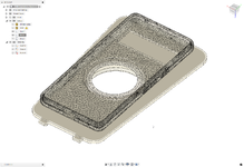
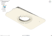
I designed a fancier plate and 3d printed it out. Don't judge me too much, it is my first 3D printer project ever. Also - I purposefully left it kind of with the rough sanded finish on top because I think it goes well with the bike - instead of shining it up...
View attachment 14207 View attachment 14208
View attachment 14209 View attachment 14210
")
I have found a 3d printer file for a cubby for the space. I posted it today.Definitely a more practical and simpler use of that space...
There's an enormous amount of room, once you pull the phone cradle out; I'm surprised a company hasn't offered a third party solution, in lieu of the over engineered OEM platform.
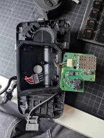
It's basically 12 V DC to power the whole assembly; the "data lines", I would guess is a temperature sensor which drives the fan speed controller ...while disassembling this part so i could actually 3D scan it and figure out the connectors - i ripped out the circuit board to take a look at the pins - and realized the data lines is actually connected on the USB port.. anybody have any idea why that would be?
Well those datalines actually connects to the phone thru the USB-C connector.. So might be some form of sensor reading and logic.. But not sure how that handshake would work.. The fan controller has a small "heat sensor" that runs thru up the board and on the backside u see a small "vent" like a circular shape with four openings on its side. Figured out the base shape now at least, so gonna try 3D print a couple of holders for different chargers and see what works best..It's basically 12 V DC to power the whole assembly; the "data lines", I would guess is a temperature sensor which drives the fan speed controller ...

 www.quadlockcase.eu